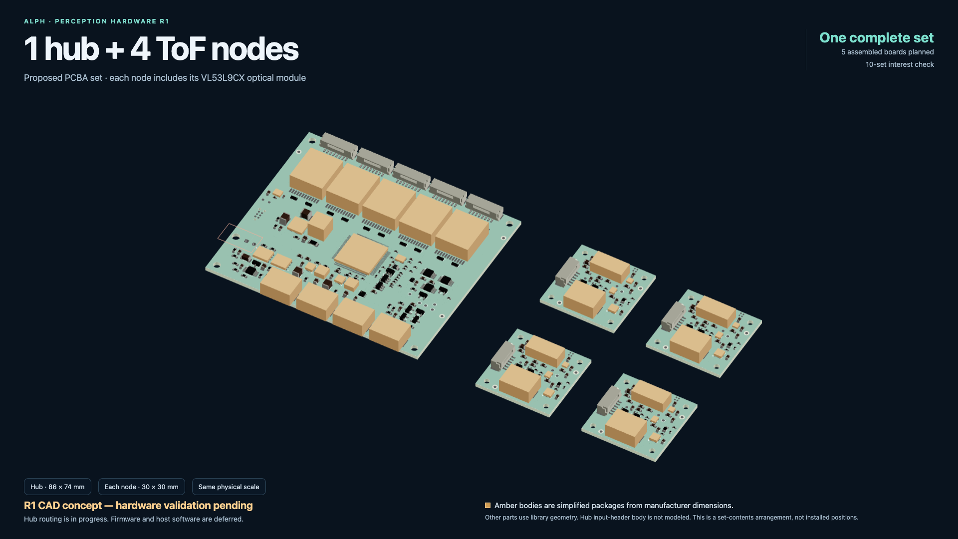
Meet the perception hub and four complete depth nodes. Their local viewer and documentation are ready; hub routing and the newer enclosure still need engineering work.
Design
R4 candidate placement reviewed; all boards unrouted
Integration
Changed mechanical interfaces received; full hood/module service unqualified
Physical build
No manufactured or populated boards yet
Board designs
Body + fender
Perception R1
Node checked / hub: 87 connections open
Fender board
80 × 60 mm · four layers
From lamp envelopes to board designs.
The first lighting pass reserved space for controllers inside the robot. The dedicated electronics work now gives the body and fenders their own native KiCad board designs.
The preserved R2 body had seven unfinished connections. Its successor R4 now targets two white channels, eight red channels and both servo feeds, with the IMU connected directly to Pi. Recorded capture checks are complete, while placement, routing and physical operation remain open.
The earlier R2 body controller targeted four white-light channels, eight red accent zones, two servo feeds and inertial sensing. The new R4 body targets two white channels and eight red outputs. Each R3 fender controller retains two white channels and two red zones; motor power bypasses the lighting boards.
The R3 fender interface is now received in completed R12 v5 CAD. Front and rear COB cassettes have captured lenses, while the lower enclosure keeps its sloped inner shoulder. Conditional board removal is documented; motor-plug and wired inner-cover extraction still have failed tested paths. Harness construction, factory processes and physical behavior remain open.
Presentation complete / engineering incomplete
See the boards. Keep the engineering gates visible.
The separate local viewer now shows an 86 × 74 mm six-layer hub and four 30 × 30 mm four-layer nodes at equal scale, plus individual board faces and package approximations. Each complete node includes its VL53L9CX optical module. The hub closed three boot/UART joins but still has 87 unfinished connections. Its actual saved refill records zero physical-rule errors and 228 warnings; full timing/reference, firmware and physical validation remain open. Ten proposed sets would mean ten hubs and forty nodes, as an interest plan with no order, selling price or delivery commitment. Six saved robot-part export comparisons pass, but enclosure fit, closure, cap-seat stock and absolute carrier volume remain unresolved. The newer 142-part enclosure image is an incomplete correction concept, not a new native design or live revision.
Node layout checked / hub paused / no fabrication release
Finish one board. Preserve the rest honestly.
The30×30mm node board has 0 source-reported unconnected items and 0 DRC errors, native reload/parity and a verified unreleased export packet. Hub routing has 27 of 40 critical Ethernet/timing/IMU nets connected in its saved scope, with 13 plus other wiring unfinished and final receiving still pending. The builder paused PCB work for manual restart. Six CAD parts and seven appearance changes are preserved but unpublished; workspace R6 remains live. Firmware, supplier acceptance, manufacturing and physical tests remain open.
Revision in progress / no final successor handoff
Make the service face flat and fully enclosed.
The builder approved service-board edge and flex changes for a flat cover with flush service ports. Earlier R6 mechanical receiving remains dated history; the revised board, flex, cover and neighboring interfaces still need their own receiving. Hub/node PCB work continues separately, with 6 mm standoffs now accepted and firmware deferred. No new manufactured, powered or completed whole-robot result is established. Saved viewer feedback also requests closed carrier walls, enclosed service internals and a continuous cover over the return cable/bracket.
Architecture agreed / hardware in progress
One hub. Four depth sensors. Five network ports.
The builder chose an integrated Gigabit/PTP hub with a perception IMU, monitoring and four powered VL53L9CX nodes. Compact locking links target1 m each. The latest choice adds a fifth external Ethernet port; AIRY, Pi and Jetson receive power separately. Protected BMS input, dry fixed mounts and 60°C passive local-air operation are targets. Firmware is deferred. The earlier four-port two-sided study is concept history; final layout, routing, manufacture and physical qualification remain open.
Scoped review CAD complete / physical and electrical gates open
The review notes now have concrete dispositions.
The SMLib batch delivers corrected fenders, cap fastener/tool access, an enclosed AIRY shroud and USB-C above Ethernet. Workspace R6 then levels both complete leg-well light mounts at the original optical height. All 69 notes are Ready for review. The seven R4 boards remain unrouted, with full hood/module removal and electrical/physical qualification still open.
Read-only audit complete / R8 not ready to build
Capture checks do not finish the system.
The frozen R8 candidate preserves 52 notes and 22 images but is unfinished. Electrical capture and a tested shutdown specification are separate from routed boards, deployed firmware and usable interfaces. Custom data paths, loaded CAN timing, shared sensor frames, heat/RF and real service still need work; R7 remains the completed local review.
Service module in progress / no final handoff
Bring the service ports and power button together.
I asked for a custom XT30, USB-C and Ethernet cluster beside the LiDAR, preferably with a small power button in the same place. I chose full USB 3 and recovery access, orderly shutdown before removing robot-load power, and charging available while off. Internal soldered tails are allowed. The new board, housing and power control are being designed; R7 remains the completed local review, the seven existing R4 boards remain unrouted, and native/physical qualification stays open.
Review CAD delivered / all R4 boards unrouted
Turn marked feedback into a cleaner enclosure.
Fourteen marked repairs are delivered: protected rear-panel ports, corrected shell transitions, enclosed inner fenders, matching dark finishes and improved fastener access. Camera USB is hidden inside the eyebrow, and both display USB routes are rebuilt. All 44 notes and their saved views remain available. Seventeen inherited structural contacts, native robot integration and physical qualification remain open.
Enclose the inner fenders and move the hip lights.
The final review R6 handoff delivers enclosed inner skins, uncrossed tibia CAN routing, forward-facing fender lamps and higher/outboard hip accents. The whole review retains thirty notes and has editable changed-part CAD plus browser verification. Physical wiring/light tests, manufacture and native robot integration remain open; seven R4 PCBs remain unrouted.
Overnight design / relevant local engineering active
Route the wire first. Enclose the fender around it.
The builder asks for enclosed inner fenders, a tight tibia-hugging route with uncrossed CAN paths, forward-facing lamps, and higher/outboard hip red accents. Relevant overnight engineering is authorized and active. No new final robot revision, routed PCB set or physical light result is complete.
Local visual candidate / engineering paused
Slim the covers and keep the light faces open.
The completed local feedback v3 pass responds to nine additional notes with thinner fender covers, protected cable channels, open lamp faces and redistributed fasteners. Saved-view and nearby static checks are recorded. The complete native robot, motion/service and physical qualification remain pending; R3 receiving and all seven unrouted R4 candidates retain their separate stages.
E04 V7 local acceptance / all boards unrouted
Clear the connector locally. Recheck the complete assembly.
E04 V7’s changed sideways J2 interface has passed its recorded native, geometry and local receiving checks. The limited acceptance retains 36 inherited DRC findings and 277 unrouted connections. Revised upper-body geometry, whole assembly/native installation, full harness and powered qualification remain open.
Engineering candidates / unrouted
Seven boards, one receiving handoff.
The body, Pi interposer, depth regulator, ST adapter, PDU, charge interface and E04 carrier have a bound receiving index. All 57 recorded native capture/cross-board checks pass, while every candidate remains unrouted. Placement findings, model/contact registration and full chassis/service fit remain visible.
R4 capture / placement in progress
Separate low-level control, perception and power.
Pi and the owned Waveshare 2-CH CAN HAT+ retain low-level work; AGX is the higher-level perception direction. Body R4, Pi interposer, ST depth adaptation and separate power/charging circuits are being implemented. Direct-Pi SPI IMU replaces the archived USB proposal; no routed-board or powered release is established.
Receiving CAD complete
Capture the lights and lower the enclosure.
Both fenders carry front/rear COB cassettes, captured lenses and low outboard controller enclosures. Strip targets are 100 mm front and 75 mm rear with 45° downward aim. Two board and fourteen header representations were received; complete populated references supported clearance. Actual tape, factory and physical tests remain ahead.
Checked engineering candidate
Lower connectors, same board interface.
R3 uses side-entry SH/GH and right-angle through-hole PH headers. All seven logical connections and the mounting interface are retained. The delivered board has 219 footprints and 202 fitted components. Static checks pass; enclosure adoption and factory release remain open.
Conditional harness construction
Design around real wire and service space.
The proposed sleeved input branch reserves an uncompressed Ø8 mm bundle, R25 mm bends and Ø9 mm passages. Ordinary splices are not cleared for the provisional 20 mm pocket. A custom axial proposal still needs measured diameter, insulation coverage and retention. Motor-plug and wired-cover paths remain unqualified.
Body incomplete / continuation handoff
Seven connections left at the stop.
The saved body design contains 454 footprints and 18 added local bypass capacitors. Recorded ERC, physical DRC and schematic parity findings are zero, but seven unconnected items keep its overall static result incomplete. The portable packet excludes body fabrication files. Fender static checks remain passed.
Fender engineering review
A checked fender board and mechanical reference.
The hash-bound fender design records zero electrical-rule violations, design-rule violations, unconnected items and schematic parity mismatches under its declared check settings. The board has 219 footprints, including nine added local bypass capacitors. The engineering review packet remains pending factory DFM and physical acceptance.
Earlier placement review
Native schematics and the initial placed boards.
The earlier Rev B placement studies contained 436 body footprints and 210 fender footprints. Later local bypass additions changed those counts; the checked fender handoff now contains 219 footprints.
Review handoffs
Define the architecture and source the exact parts.
Rev A architecture and Rev A.1 exact-part sourcing review packages are complete. Those deliveries define the earlier design direction; the integrated Rev B boards are now undergoing layout and routing work.
Completed receiving CAD; service and physical gates remain.
R12 v5 closes the fender receiving-CAD cycle. The board-removal workflow has conditional engineering acceptance with named manual TPU/tie handling, RH J7 package parking and numerical assumptions. Tested motor-plug paths collided; straight 25 mm inward removal of the wired inner cover failed, so accepted board service leaves it installed. R3 remains a checked engineering candidate pending fabrication approval: its portable nominal model omits 17 fitted bodies, stock PH tails exceed the ≤1.20 mm finished underside target and the NONFAB helper is not an approved dielectric stack. Complete 835-constituent references supported receiving clearance and complete-board mass was counted once. Factory processes, wiring/CAN, firmware, RF, optics, thermal behavior and first-article fit remain open. The earlier R4 capture checkpoint reported 453 physical components and 1,343 matched intended pins with zero ERC findings. These capture results do not complete placement, routing, firmware or powered acceptance. The archived R2 seven-connection state remains preserved. The later receiving checkpoint has 454 native body entries (444 populated packages, nine bare test pads and one DNP resistor) and a seven-board set. Its 57 recorded checks establish capture/interface agreement only; every board remains unrouted and unreleased. The October 10 E04 V7 addendum accepts only its changed local mechanical interface; it does not close whole-assembly/native installation, routing or physical gates.
Completed R12 v5 native/archive/cloud handoff; immutable R3 candidate and harness research; separate unfinished Rev B body checkpoint. Earlier study views remain labeled historical progress. October 9 new owner direction and frozen current R4 capture/placement snapshots distinguish the active successor from historical R2 and completed R3 receiving. Latest frozen seven-board receiving index and exact remote-NTC selection replace superseded initial placement/map summaries. October 10 frozen receiving index and E04 V7 root addendum clarify native/populated counts and local acceptance; builder upper-body corrections require fresh combined verification. Later October 10 feedback v3 is a visual/nearby-fit candidate, not a new native robot delivery; cloud AIRY R5 is separate and awaiting local receiving. October 11 review R7 completes local marked repairs and both display USB reroutes, with 44 notes preserved and 17 inherited structural contacts still open. This changes review CAD, not PCB routing or native robot delivery.
Design views.
14 Oct 2026Completed R12 v5 CAD + PCB history
Captured lights. Lower controller enclosures.
+
Proposed PCBA set / hardware validation pendingOne hub + four complete nodesOne proposed set at the same physical scale: an 86 × 74 mm hub and four 30 × 30 mm nodes, each including its VL53L9CX optical module. This is a set-contents arrangement, not installed positions. The hub uses frozen 02a preview geometry; later copper is not shown. Amber packages are simplified, and hub J1 has no verified body.Checked node source / local viewer screenshotNode R1 · Inspecting the fitted packagesSaved screenshot from the separate local PCBA viewer, bound to node 400dd. All 61 fitted references have library or simplified package bodies; ten are simplified. The drawing supports presentation, not toleranced mechanical or powered sensor acceptance.Frozen hub preview / routing incompleteHub R1 · Placement previewThe local viewer shows the frozen 02a placement snapshot, not the later b0fc routing result. Twenty-six package bodies are simplified and the J1 input-header body is missing. Routing, signal-reference, firmware and physical tests remain open.Correction concept / not a new native candidateEnclosure · Full context for the next correctionA 142-part context study adds the hatch, fasteners and affected neighbors omitted from the earlier preview. Colored translucent regions are proposed envelopes over saved meshes. The concept is incomplete, unaccepted and has no new native geometry; closure, seat stock, capture details and service access remain unresolved.Checked node layout / unreleased engineering candidateNode R1 · Both assembly facesSaved assembly views of the checked 30 × 30 mm node 400dd candidate: top at left, mirrored bottom at right. Routing/native/export checks are source results. It is not fabricated, factory-released or physically qualified; firmware remains deferred.Earlier partial preview / coverage incompleteEarlier six-part preview · Incomplete contextOctober 14 six-part study. Later review found omitted affected neighbors, so this view does not qualify complete coverage. Relative export comparisons subsequently passed, but assembly, closure and absolute carrier volume remain unresolved. See the October 15 full-context correction concept; the live model stays workspace R6.Earlier four-port concept / before five-port directionEarlier study · Both board facesCompleted 85 × 60 mm four-port, 10–60 V planning study, before the builder added a fifth external port and the input target became 8–60 V. Blocks and mounting allowances are provisional; this is not the current native PCB, routed design or manufactured hardware.Completed SMLib review CAD / builder acceptance pendingWorkspace R6 · The complete review modelCommitted SMLib workspace R6 after fresh browser reload. All parts are visible in this whole-robot view. The selector retains the older R8 feedback-branch name; the committed revision is r000006-75cd786c. Physical acceptance and Fusion integration remain open.Completed SMLib review CAD / builder acceptance pendingWorkspace R6 · Inspect the internalsThe same committed R6 with two parts hidden in the preserved inspection view. This shows the current modeled electronics and wiring; hidden geometry does not prove teardown access or electrical operation.Completed SMLib review CAD / builder acceptance pendingWorkspace R6 · Level light mountsBoth complete accent-light housings and mounts were corrected to level at the original optical height. Native receiving supports the orientation; this perspective image is a review view, not an angle measurement or powered-light test.Completed R12 v5 native CADR12 v5 · Front cassette and low enclosureCaptured front COB lens/cassette and low outboard controller enclosure in the completed native CAD. Tape, heat, optics, factory fit and service handling remain unqualified.Completed R12 v5 native CADR12 v5 · Integrated rear lightingRear light cassette follows the fender profile in the delivered CAD. The 75 mm strip is a target requiring actual tape verification; no powered result is shown.Earlier Candidate 193 study / before final handoffIn progress · Front lighting and the lower enclosureCandidate 193 CAD study: front accent lighting is integrated into the fender edge above the wheel. LEDs are shown unpowered; materials are illustrative. Final native adoption and physical fit remain pending.Earlier Candidate 193 study / before final handoffIn progress · Matching rear lightingCandidate 193 CAD study: rear lighting and the refined outer panel follow the fender profile. This is a work-in-progress render, not a completed robot revision.Earlier Candidate 193 study / before final handoffIn progress · Inside the controller enclosureCandidate 193 inspection render with the lid and lid bolts hidden. Nominal PCB/component and wire reservations show packaging intent; missing component models, complete service access and physical fit remain open.Earlier Candidate 193 study / before final handoffIn progress · A closer look at the cable guideCandidate 193 isolated CAD inspection: neighboring robot structure is hidden to show the guide and retained actuator leads. This is not an achieved service state or a qualified cable assembly.Checked engineering candidate / not fabricatedR3 · Low-profile fender PCBDelivered PCB review shows component placement and four copper layers. Side-entry connectors retain the board interface; static electrical checks pass. Enclosure receiving, factory processes and physical behavior remain unqualified.Checked static design / reference onlyRev B · Checked fender mechanical referenceSource-bound reference for the checked 80 × 60 mm PCB, mounting pattern and nominal antenna/component envelope. Factory DFM, connector mating, stack tolerances, enclosure adaptation and physical qualification remain pending.PCB study / unfinishedRev B · Fender board placementIntermediate fender controller component placement. Copper routing and final release checks are underway; this image does not represent a finished or manufactured board.R12 CAD context / board fit pendingR12 · Lighting enclosure contextCompleted R12 compact CAD shows the existing lamp and electronics-lid geometry. The new Rev B fender board is larger than the earlier allowance and requires internal adaptation; board fit is not established by this image.
Parts for this design.
Current R3 fender selections and the separate Rev B body checkpoint, alongside robot lamp context and explicitly proposed harness materials. This is a working index, not the complete manufacturing BOM.
The finished design is intended to be open-sourced. Repository, license and release approval are still pending. Downloads will identify the exact component revision they belong to.
Lighting & PCBA planned file releases
File type
Design revision
Availability
Notes
KiCad schematic + board projects
Rev B / body incomplete
Planned
Checked fender review is preserved; body fabrication files excluded. License, factory DFM and public release approval remain pending.
Schematic PDFs + firmware requirements
Rev B / body incomplete
Planned
Checked fender review is preserved; body fabrication files excluded. License, factory DFM and public release approval remain pending.
Fabrication + assembly package
Rev B / body incomplete
Planned
Checked fender review is preserved; body fabrication files excluded. License, factory DFM and public release approval remain pending.
KiCad + nominal STEP + harness notes
R3 low-profile fender
Planned
Checked engineering candidate only. Public license/release approval, factory processes and final integration remain pending.
KiCad + adapter/power projects + interface notes
R4 body / interface successor
Planned
Active capture/placement only. Final engineering handoff, license and public release approval remain pending.
Native CAD + STEP + mechanical review notes
SMLib workspace R6 · October 13 review
Planned
Scoped mechanical receiving is complete. Builder design review, repository, license and public release approval remain pending; electrical and physical qualification are separate.
KiCad + schematics + hardware interface documents
Perception hub + nodes R1 · in progress
Planned
Completed local presentation uses frozen 02a geometry. Hub routing still has 87 unfinished connections; factory, firmware, physical, license and public-release gates remain open.
Node KiCad + schematics + review documentation
Perception node R1 · checked routing candidate
Planned
Exact node 400dd layout/export checks retained. The local presentation is complete, but its private packet remains unreleased; firmware, factory, optical/physical, license and release approval remain pending.
Working BOM CSV downloads above are available now. Editable design and manufacturing packages will be linked after release approval.