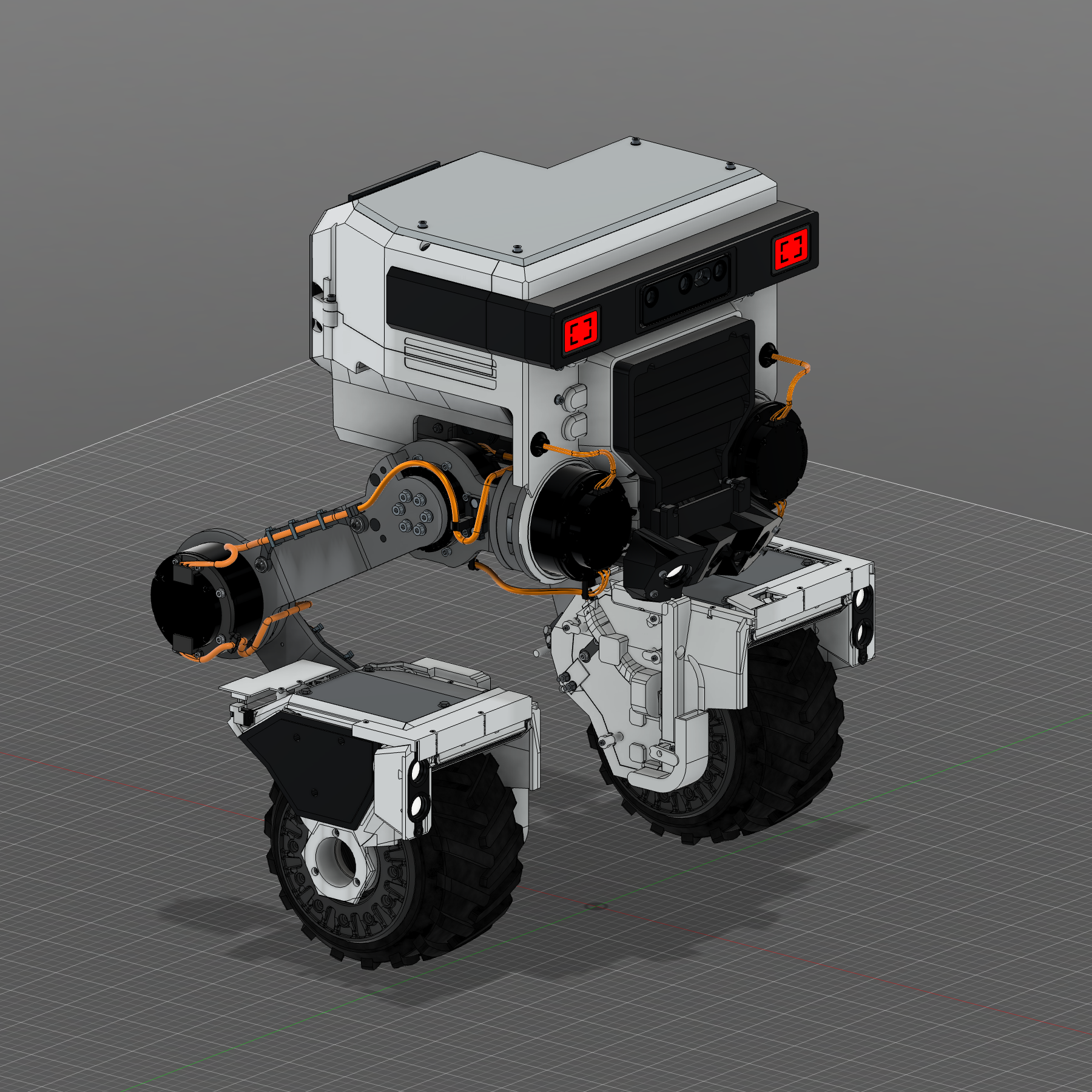
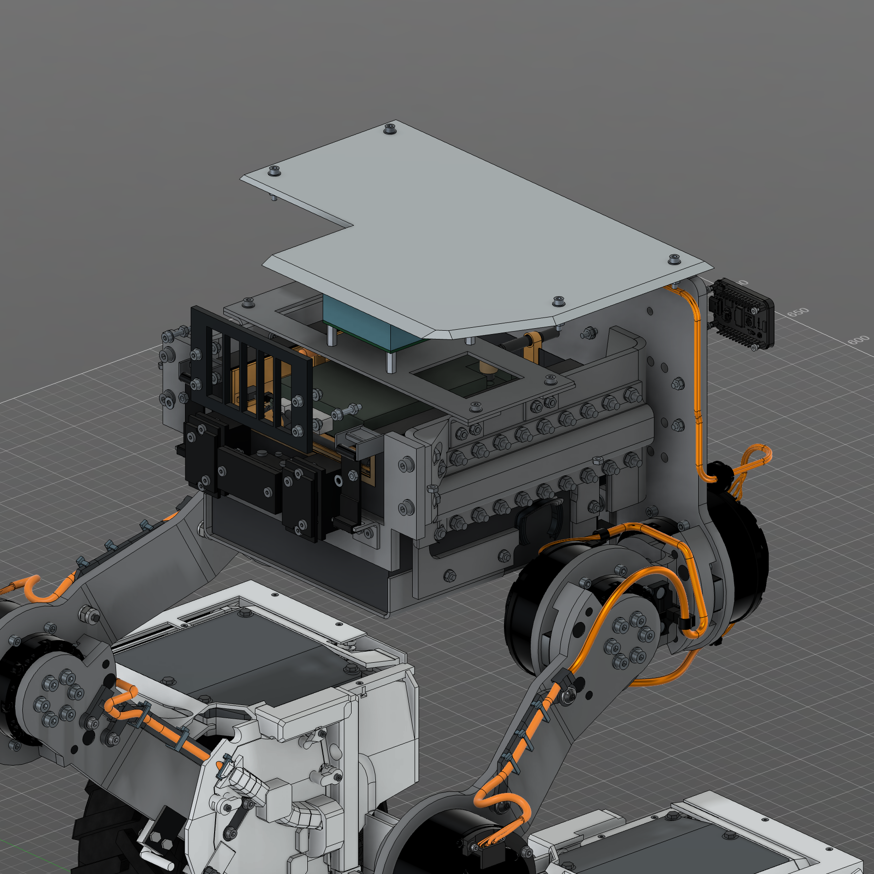
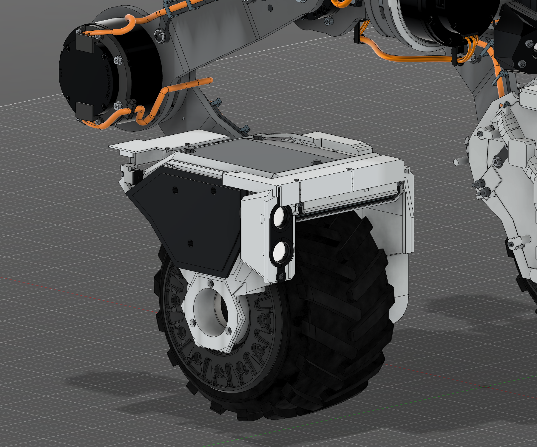
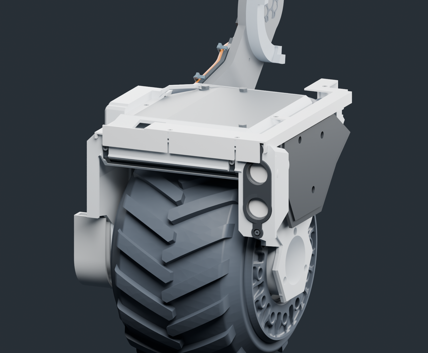
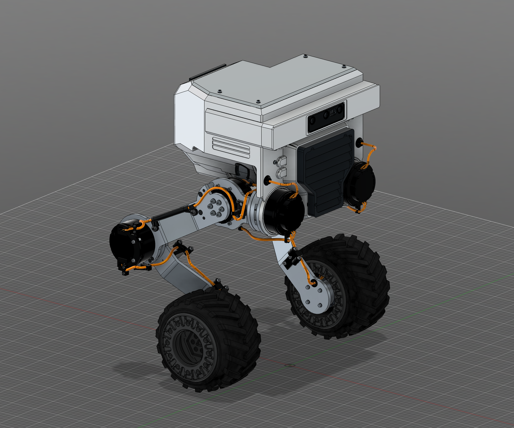
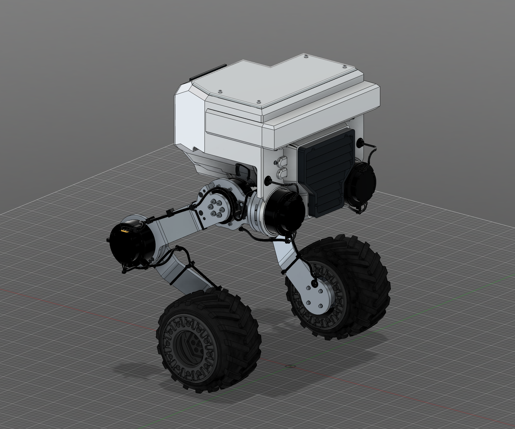
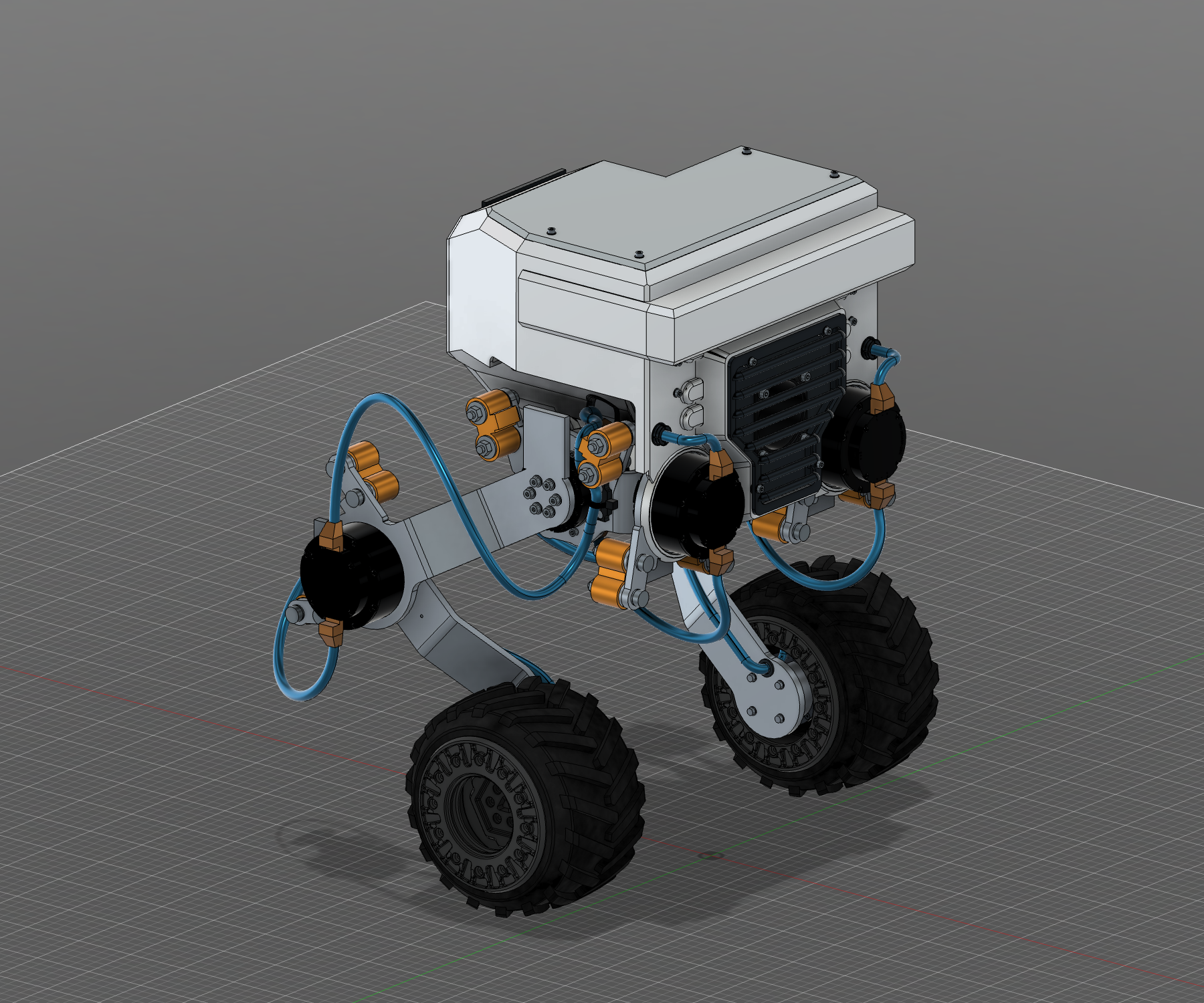
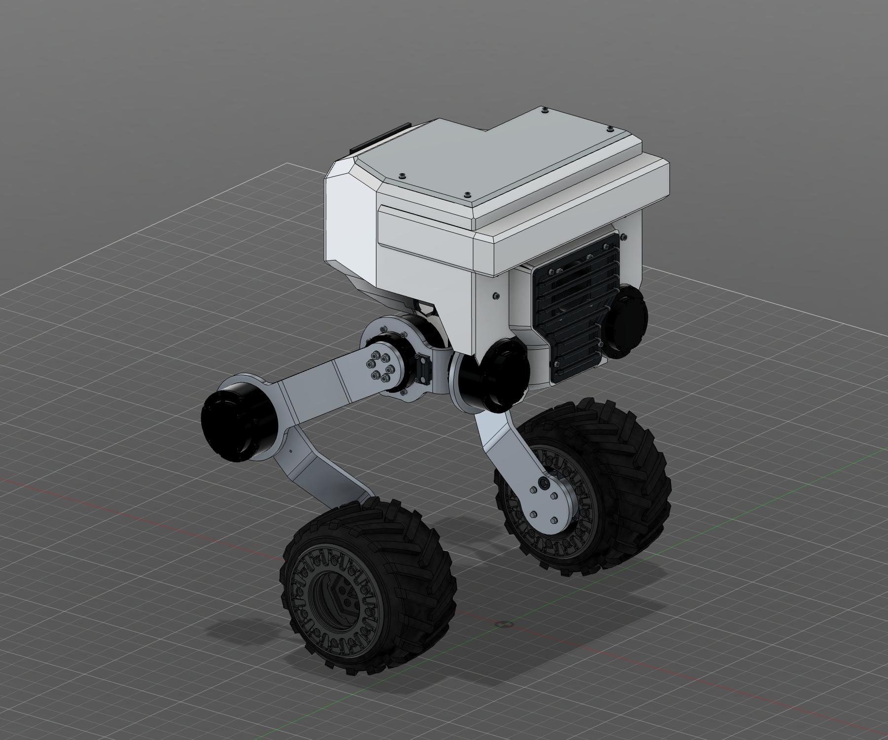
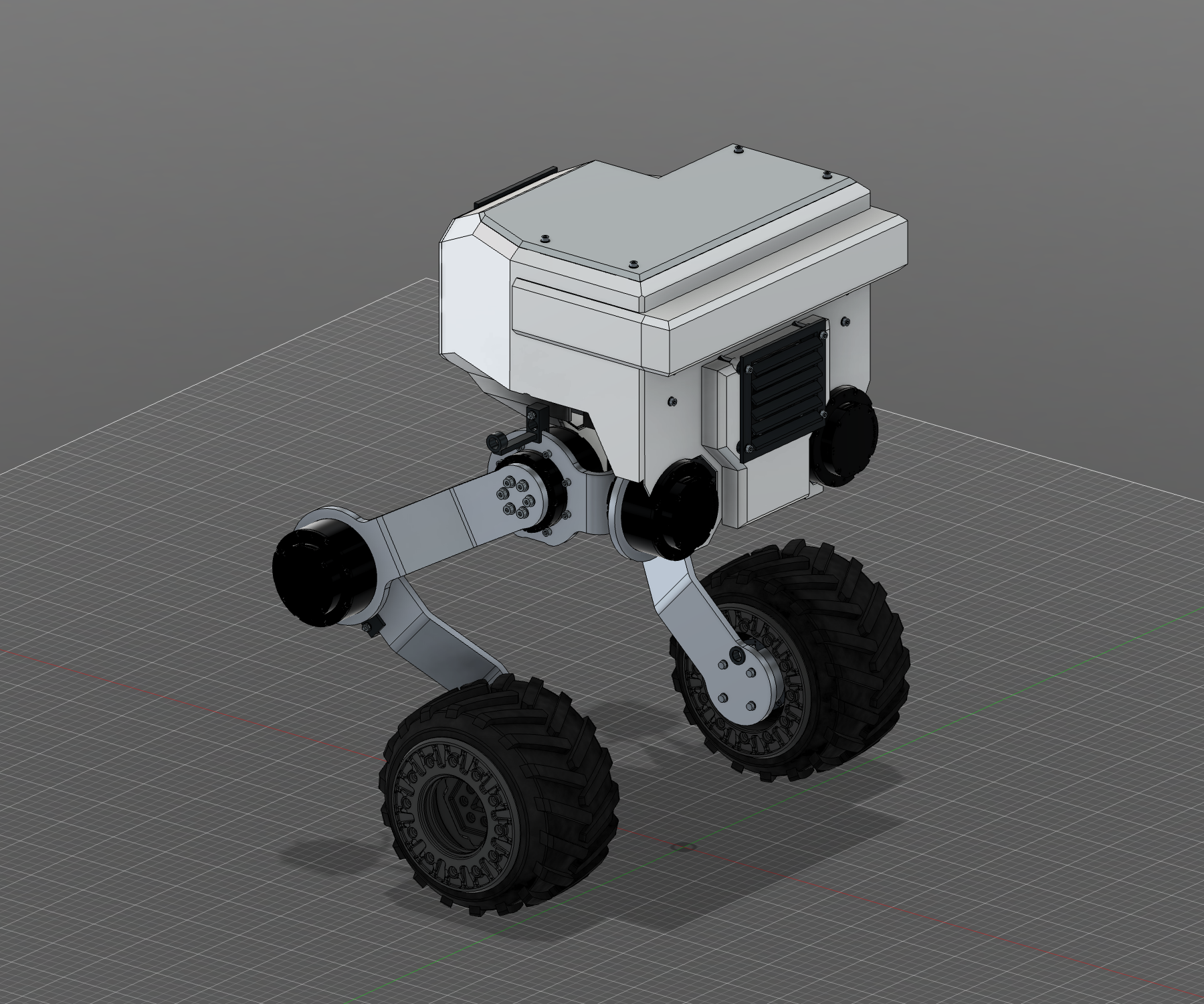
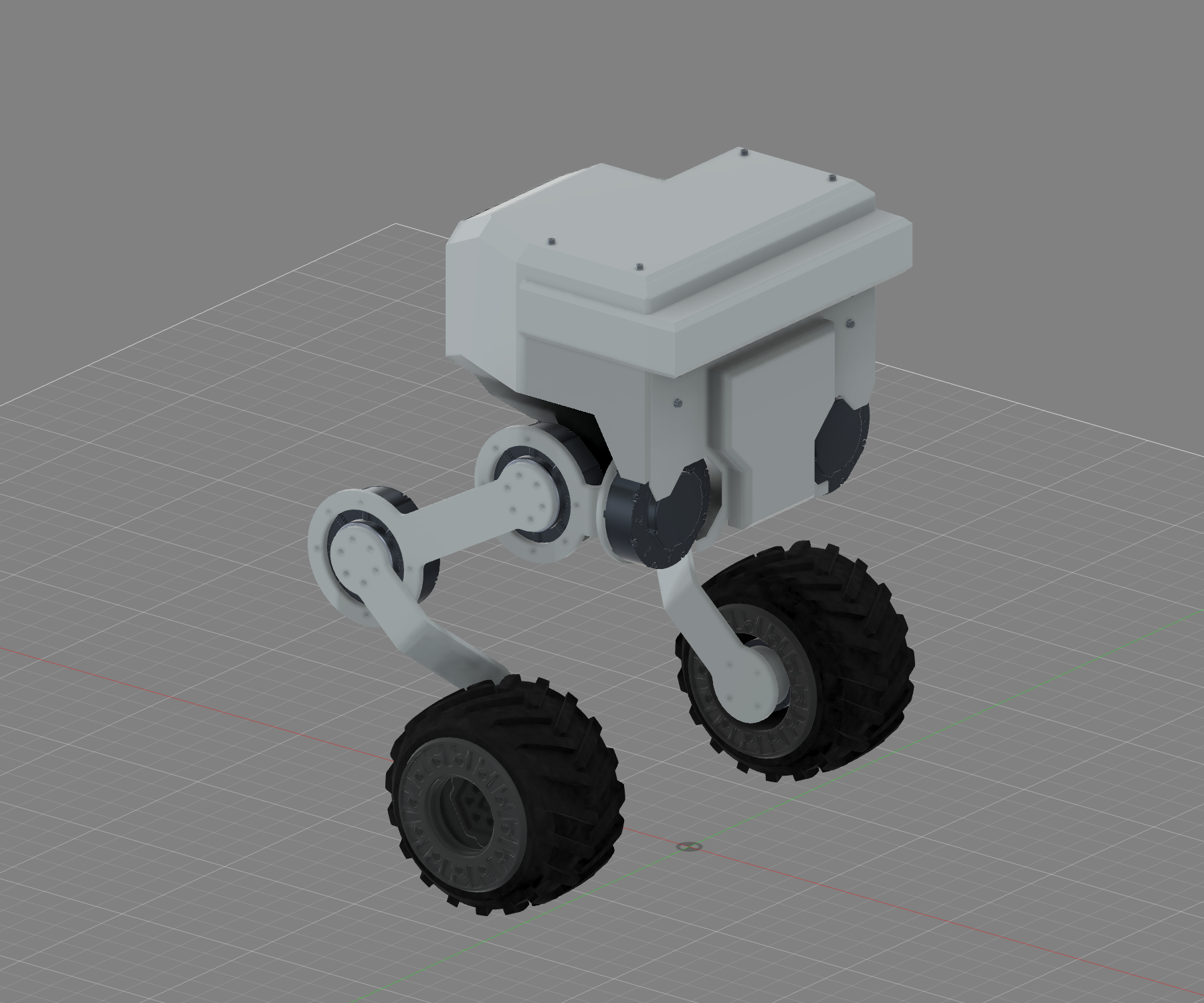
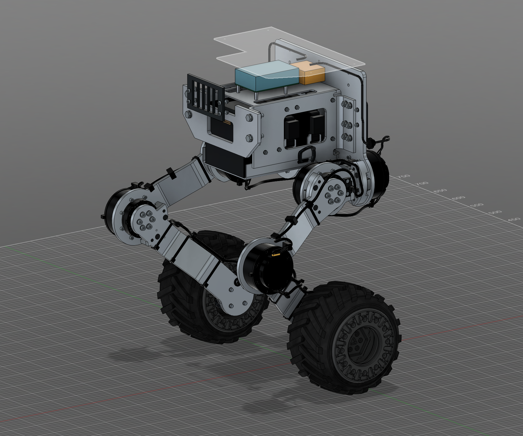
I was selected for an OpenAI developer program to demonstrate what I can build with Codex. It’s just me and Codex designing Alpha Rolie—a compact wheeled biped that we’ll build, bring up, and train together.
The OpenAI developers team is sending a special Codex-branded Raspberry Pi 5 for low-level onboard compute.
The decisions. The revisions. The work in between.
A growing record of how Rolie takes shape. Start with the latest revision, or open an earlier entry to follow a decision back to its source.
September 27 — October 9, 2026Latest first / 20 entries
R4 PCBAEngineering candidates / unrouted
Seven boards, one receiving handoff.
The new electronics now have a common interface and placement checkpoint.+
The PCBA work has brought seven candidates together: body controller, Pi interposer, depth regulator, ST adapter, power distribution, manual charge interface and the E04 power carrier. The receiving packet records 57 passed native capture and cross-board checks.
That gives the robot-design work a more concrete set of boards, interfaces and nominal geometry to receive. It also keeps the unfinished work visible: every candidate remains unrouted, and documented placement findings, actual connector registration, full mated fit and service paths still need resolution.
The body-lighting map now targets four leg-well/ground strips and two grille strips, with two spare channels. A specific SEMITEC remote lamp probe is an engineering candidate; its exact conversion profile, insulated lead mounting and physical thermal response still require qualification. These are design selections, not new purchases or operating results.
R12 version 5 remains the completed robot CAD baseline.
This is a component receiving checkpoint. Main robot integration is still active; no new final assembly, routed fabrication release, firmware commissioning or powered test is established. Conservative component-space envelopes remain separate from actual material models.
Build records: completed PCBA receiving handoff, current bound index and source verification; active combined robot/PCB work. All 102 index-bound artifact references matched at review.
Next directionDesign in progress
Give Rolie more to see.
Higher-level compute, two new depth-sensing paths and a body electronics successor.+
I want the Pi to keep handling low-level control while a Jetson AGX Orin handles higher-level perception. The current direction adds RoboSense AIRY at the rear-left head recess and a downward-facing ST depth sensor between two wide chin spotlights. I already have the Waveshare 2-CH CAN HAT+ for the Pi; actual traffic and stack fit still need qualification.
The hardware needs to look designed into the robot. AIRY should be centered and fully supported by angled panels and chamfered edges matching the body. The chin sensor and lights should be captured within the body/grille on hidden rigid support. The fenders need covered wiring, substantial direct tibia attachment, detailed lids and a slim cable cover.
Body R4 separates control, direct-Pi IMU sensing and compute-power interfaces from the retained fender boards. Circuit-capture checks have passed; board placement and routing remain underway. Concealed red accents above the legs, beneath the body and possibly behind the grille are part of this next cycle.
Charging should be accessible through a rear-left XT30 while the pack stays inside, using my adjustable voltage/current supply and the protected battery/BMS path. Ethernet/USB-C and future docking space are reserved for later; no dock or powered charging result is established.
R12 version 5 remains the completed CAD baseline.
This entry records builder-approved direction and active component work. It does not announce a new robot revision, routed production board, manufactured hardware or working perception system. New geometry still needs accepted integration, complete verification, archive reopening and cloud handoff.
Build records: October 9 builder direction and exterior-review corrections; frozen source snapshots of current R4 capture/placement work. Rejected geometry studies are not presented as the selected design.
R12 · v5Verified CAD handoff
The battery, frame and lights come together.
A rebuilt 6S6P chassis, captured front/rear light cassettes, and low controller enclosures in the saved robot assembly.+
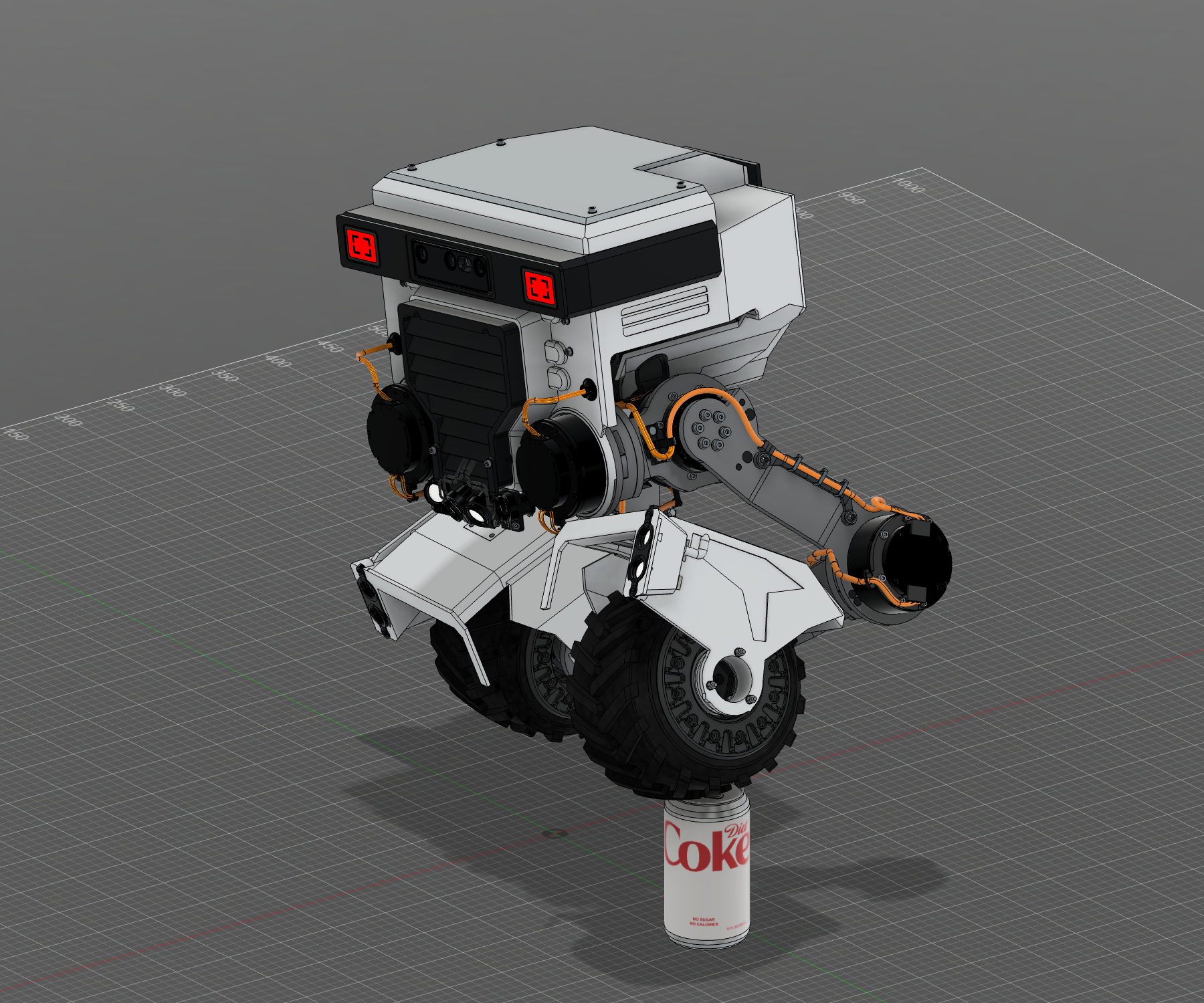
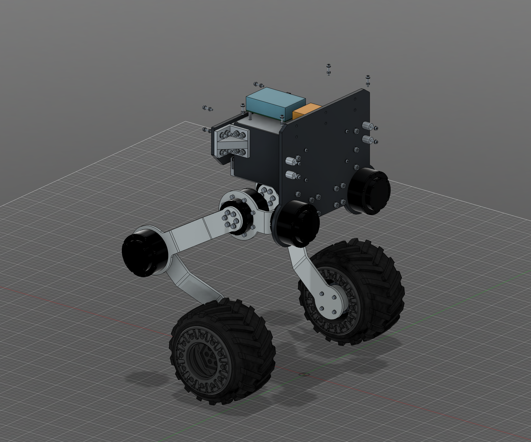
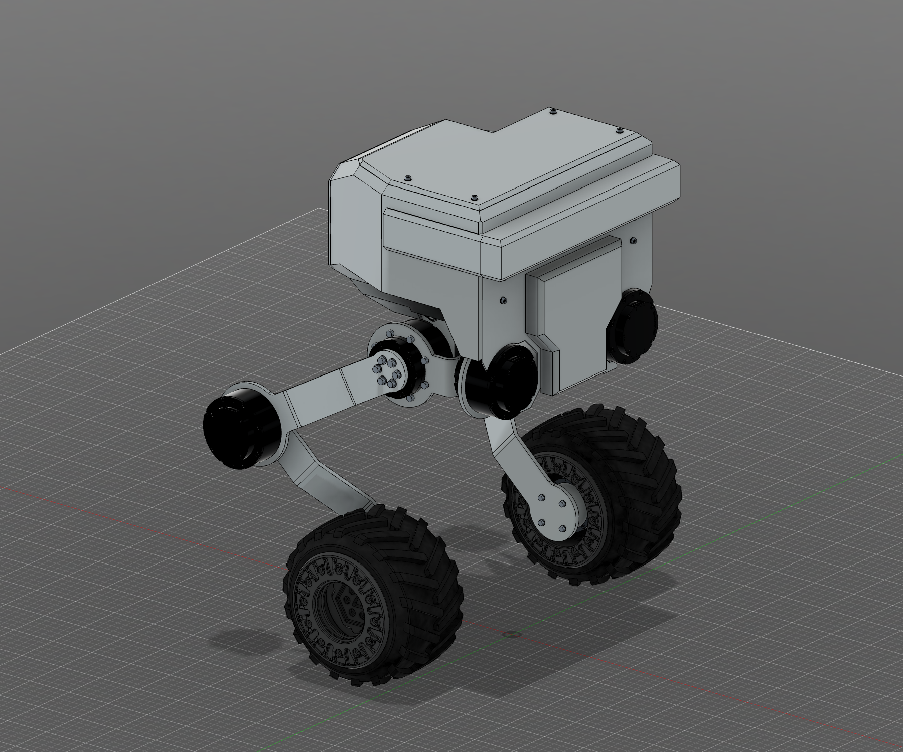
Completed R12 v5 native CADR12 v5 · Completed assemblyThe saved R12 version 5 native CAD assembly: rebuilt battery chassis, profile-following fenders and integrated light cassettes. This is a CAD capture, not a physical robot.Completed R12 v5 native CADR12 v5 · Front cassette and low enclosureCaptured front COB lens/cassette and low outboard controller enclosure in the completed native CAD. Tape, heat, optics, factory fit and service handling remain unqualified.Completed R12 v5 native CADR12 v5 · Integrated rear lightingRear light cassette follows the fender profile in the delivered CAD. The 75 mm strip is a target requiring actual tape verification; no powered result is shown.Completed R12 v5 native CADR12 v5 · Battery and receiving chassisCompleted receiving CAD around the 6S6P pack. Exterior covers are hidden for this visibility illustration; it does not establish a physical teardown sequence.Completed R12 v5 native CADR12 v5 · Chin lights and rounded transitionsRadiused hip transitions retain the established web mounts. Four chin lamps aim 30° downward with 10° inner / 15° outer outward yaw; physical optics and attachment still require qualification.
R12 version 5 brings the battery, chassis and lighting work into the completed saved assembly. The frame now fits the complete 6S6P pack, with braced cheeks, inward returns and a supported tray. Both fenders carry integrated front and rear COB cassettes with captured lenses.
Low outboard controller enclosures keep their sloped inner shoulders and removable caps. The armor follows the fender profile, while rounded hip transitions retain the existing chassis mounts. Four chin lamps now aim 30° downward, with outward yaw of 10° for the inner pair and 15° for the outer pair.
The front/rear strip targets are 100/75 mm at 45° downward aim; actual delivered tape still needs verification. Modeled robot mass is 16.95 kg, excluding optional sensor reserve and unmodeled main-body power-interface/distribution hardware. It is not a weighed result.
The completed CAD has receiving and persistence evidence.
All 723 incoming original-source comparisons passed. Native joint motion, actual editable-F3D reopening and a second repeatable archive verification passed. Cloud version 5 completed from one save. A separate cloud download/reopen was not performed; physical fit, fabrication, electrical behavior and balance remain future evidence.
Board removal retains conditional engineering acceptance with named manual handling and numerical assumptions. Tested motor-plug paths collided, and straight inward removal of the wired inner cover failed. The accepted board-service sequence leaves that cover installed. The body PCB still has seven unfinished connections.
Build records: completed October 9 at 12:04 pm Central; R12 v5 final manifest and handoff, actual native/archive verification, source-bound captures and owner recordings.
ComponentsR3 fender / integration active
Inside the next fender.
New front/rear lighting studies, a checked low-profile PCB candidate, and the resumed battery/chassis cycle.+
Earlier Candidate 193 study / before final handoffIn progress · Front lighting and the lower enclosureCandidate 193 CAD study: front accent lighting is integrated into the fender edge above the wheel. LEDs are shown unpowered; materials are illustrative. Final native adoption and physical fit remain pending.Earlier Candidate 193 study / before final handoffIn progress · Matching rear lightingCandidate 193 CAD study: rear lighting and the refined outer panel follow the fender profile. This is a work-in-progress render, not a completed robot revision.Earlier Candidate 193 study / before final handoffIn progress · Inside the controller enclosureCandidate 193 inspection render with the lid and lid bolts hidden. Nominal PCB/component and wire reservations show packaging intent; missing component models, complete service access and physical fit remain open.Checked engineering candidate / not fabricatedR3 · Low-profile fender PCBDelivered PCB review shows component placement and four copper layers. Side-entry connectors retain the board interface; static electrical checks pass. Enclosure receiving, factory processes and physical behavior remain unqualified.
These new views come from the current fender CAD candidate: front and rear accent bars, a lower enclosure, and controller packaging beneath its cover. The images are source-bound work-in-progress renders. They show design intent; final native adoption, service access and physical qualification are still being checked.
The fender controller now has an R3 engineering handoff. All seven connectors use side entry, supporting my request for a lower enclosure. The 80 × 60 mm board outline, mounts and nonconnector geometry stay the same. Its recorded native electrical, routing and connectivity checks pass; the earlier fender remains preserved.
The mating housings and contacts are selected, and the input harness has a concrete material proposal: an uncompressed Ø8 mm sleeved bundle, R25 mm bends and Ø9 mm clear passages. Those are engineering reservations. Actual terminations, source protection, actuator pin mapping, complete CAN topology and finished dimensions still need qualification.
I resumed the main CAD work after the travel checkpoint. The receiving chassis and low-profile fenders are being integrated. PCB-removal analysis has progressed within stated numerical and handling assumptions; tested motor-plug and wired-cover removal paths collided and remain unqualified for physical service.
The completed robot baseline remains R12 version 4.
R3 is the fender PCB revision, a checked candidate pending factory approval and physical acceptance. The body board still has seven unfinished connections. The active CAD cycle has no final whole-robot handoff yet. Ordinary splices are not cleared for the 20 mm pocket, and a custom axial proposal still needs measured diameter and retention.
Build records: October 9 immutable R3 fender engineering handoff; later harness and transition research; explicit builder continuation and active CAD progress.
CheckpointIncomplete / preserved
Stop with the work preserved.
A verified local recovery checkpoint, an unfinished body board, and clear work for the next session.+
I had to pack up the MacBook for travel, so I asked Codex to stop and preserve the partial Fusion state. The local recovery file was reopened and checked. The redesign remains incomplete, and the completed R12 cloud version 4 is intact.
My latest review asked for a lower fender electronics enclosure, especially along the inboard top edge, and a possible outboard board offset. I also wanted the battery-support side plates tied together above the hip actuators, with the front mounting flange turned inward for a simple 90-degree bend. Those changes still need completed native integration.
The overnight electronics handoff preserves the statically checked fender controller and a body controller with seven unfinished connections. Body fabrication files are excluded. Firmware, factory review, mating harnesses, enclosure fit and physical acceptance remain open.
Recovery is a checkpoint, not a finished robot revision.
The exact partial native archive was reopened and matched to its recorded model state. No new cloud save or final integrated assembly was delivered. A small disposable import trial also qualified geometry receiving, finish, rigid movement and archive reopening for its sample; the complete assembly still needs its own checks.
Build records: October 8 builder travel stop and design feedback; verified incomplete native recovery receipt; immutable overnight PCBA handoff and continuation list.
ComponentsParallel design work
The battery and boards get their own design cycles.
A completed standalone 6S6P pack, receiving-chassis work, and integrated controller boards in progress.+
Standalone CAD / complete6S6P · Isolated pack CADComplete physical-part geometry of the standalone 6S6P design. This is a CAD rendering; fabrication and electrical qualification remain ahead.PCB study / unfinishedRev B · Fender board placementIntermediate fender controller component placement. Copper routing and final release checks are underway; this image does not represent a finished or manufactured board.
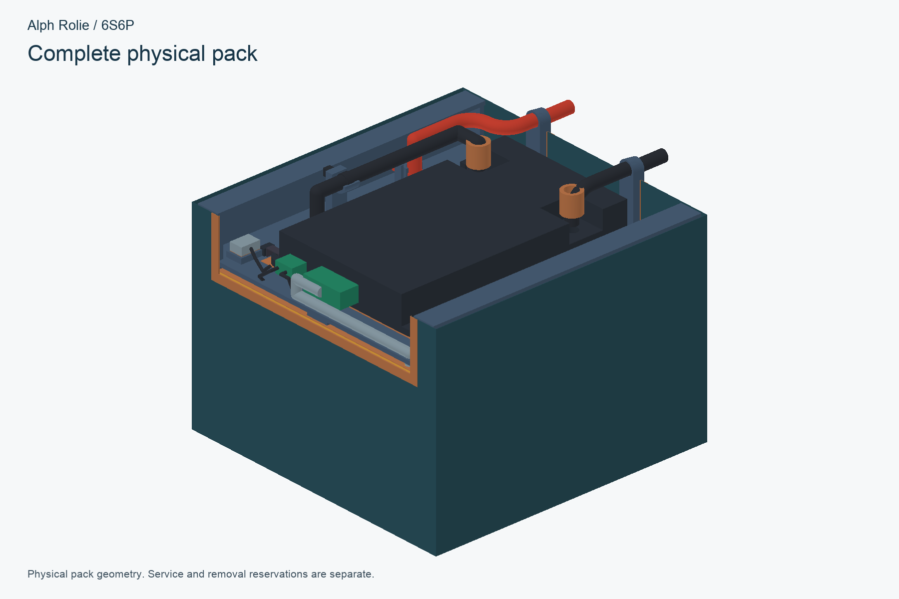
The battery is now a completed isolated mechanical design: 36 owned EVE cells in a 6S6P pack, with the owned 40 A JK BMS. Its core is 146 mm wide, with a documented interface for the chassis. Source checks and a fresh rebuild are recorded; physical fit, welds, protection and thermal/current behavior remain ahead.
The dedicated PCBA work is developing the body and fender controllers in native KiCad. The fender board now has a checked static-design handoff and mechanical reference. The body board stopped at the overnight cutoff with seven connections remaining; factory DFM and physical acceptance are still ahead. The new board outlines require their own mechanical accommodation.
The receiving-chassis and body work later stopped at a preserved incomplete travel checkpoint. R12 version 4 remains the last completed whole-robot CAD save.
Component design and robot integration have separate handoffs.
The battery’s completed interface does not establish completed main-assembly integration or physical qualification. Earlier electronics architecture/sourcing review packages are complete; the current Rev B board layouts remain work in progress. File releases, fabrication orders and first-board acceptance are separate steps.
Build records: isolated battery handoff and delivery verification; dedicated electronics work order and October 8 status snapshot; active receiving-chassis progress.
R12 · v3 / v4CAD complete
Shorter fenders. Details that can be serviced.
Protected cable passages, recessed bearing screws, and dark accents—then back to a normal standing pose.+
Native CAD / completed standing saveR12 · Normal standing / version 4The latest saved pose: body level, both tires at ground, can hidden and neutral cable displays restored. The exact standing archive was reopened; physical balance remains untested.Native CAD / completed compact designR12 · Can-reference pose / version 3Completed compact geometry in the preserved can presentation. The can gives a familiar scale reference; its strength and the robot’s powered balance still need physical testing.Native CAD / exterior detailR12 · Compact exterior and gray accentsThe nose is 25 mm shorter, with a dark removable lid, raised screw-on wire-access panel, vertical lamp pair and recessed bearing mount. Production fit and thermal behavior remain open.Native CAD / passage detailR12 · Protected tibia cable passageThe local four-core path passes through the modified tibia and matching rear adapter into the covered fender. Thread the cable before controller-end termination; abrasion and electrical behavior need physical qualification.Native CAD / bearing detailR12 · Recessed outside-in bearing screwsM3×20 screw heads sit inside the hex surround, with continuous printed bosses and insert-carrying inner retainers. Selected print geometry uses PREPRESS bearing blanks; press fit and insert retention are not yet physically qualified.
I pushed for 25 mm of nose shortening, closer inner covers, and protected cable passages through the tibia and its matching rear adapter. The finished design brings those changes into the connected assembly while keeping the original orange motor wiring.
Looking closely at the bearing support exposed a gap. We worked through recessed outside-in screws, pressed threaded inserts in the inner retainer, and continuous printed bosses. The removable electronics lids and raised outer panels now carry the dark gray accent; the outer panel also provides access to the local lamp wires.
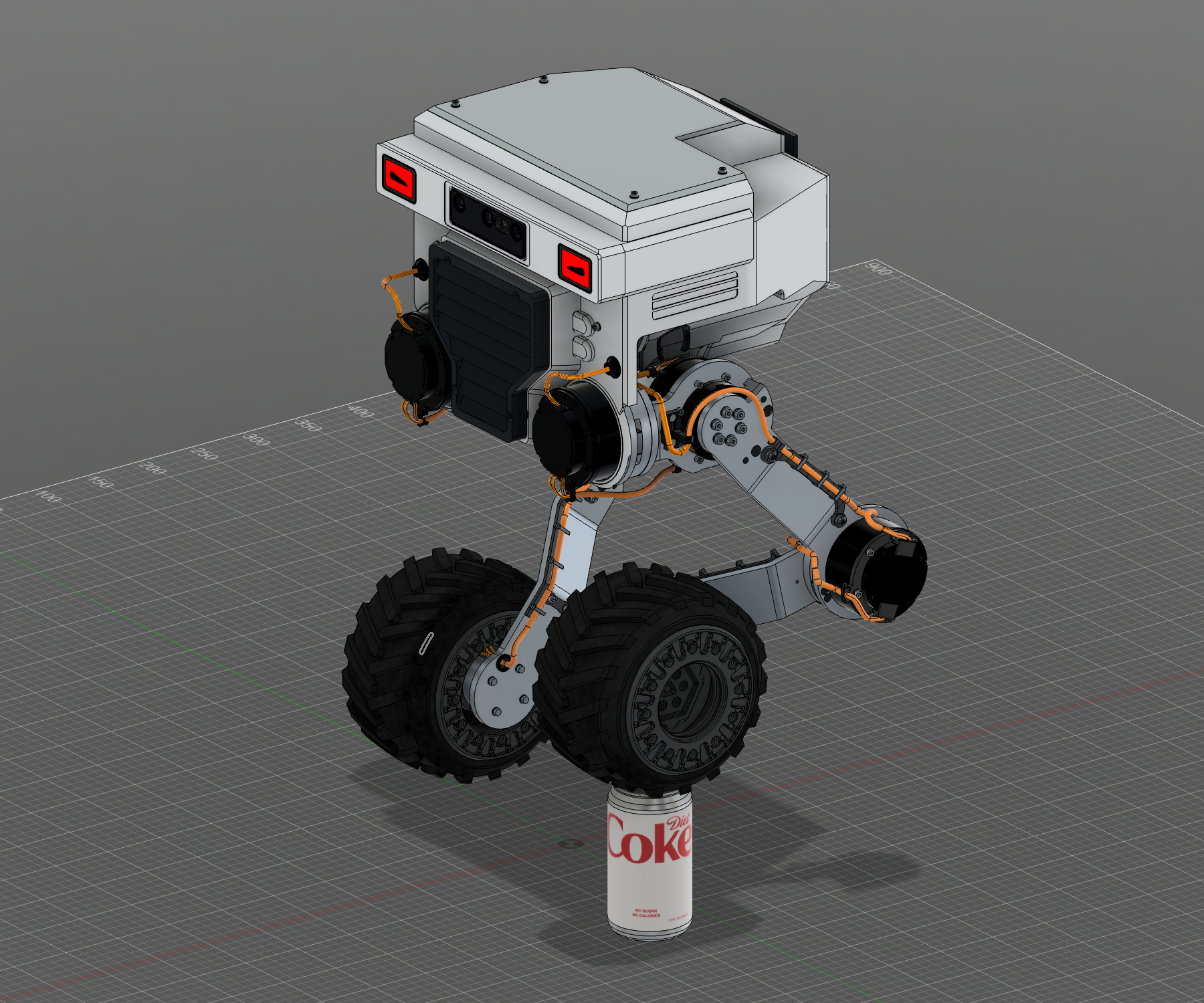
The compact design was delivered as R12 version 3. After recording the can-reference pose, I asked Codex to return Rolie to normal standing height. Version 4 saves that pose with the body level, both tires on the ground, and the can hidden. It changes the presentation, with the compact geometry retained.
Version 3 passed five native motion cases and four more after reopening the exact local archive. Offline checks cover 75 rigid articulation samples and both-wheel all-angle envelopes. Version 4 has its own completed cloud save and reopened standing archive. Independent cloud download/reopen was not performed.
Both noses are 25 mm shorter. The broad inner panel has 20 mm less projection across most sampled rays; local transitions differ, and the lamps extend farther outboard. This is not proof of an overall narrower robot. Twenty selected meshes passed software qualification; printing, fit, insert retention, bearing loads, cable life and electrical operation still need hardware evidence.
The compact-design mass model estimates 15.156 kg, with a 12.786–17.743 kg engineering range: +66.3 g from version 2. Its support study uses the can pose, not the new standing pose. These are planning estimates, not measured mass or powered balance.
Build records: October 7 completed compact-design handoff, native/archive/cloud and selected-mesh receipts, plus the subsequent completed standing-pose save. One cable’s Fusion volume was unavailable; its complete native geometry comparison passed.
R12 · v2CAD complete
Sculpted fenders. Shorter lighting paths.
Vertical lamps, covered inner mounts, and local four-wire feeds replace the long red lighting harness.+
Completed CAD / version 2R12 · Version 2 completed assemblySculpted fenders, vertical lamp pairs, concealed inner mounts, and short local lighting feeds in the preserved can stance. The long added red routes are removed; original orange motor wiring remains.Native CAD / lamp envelopesR12 · Vertical fender lampsNeutral front view shows vertical fender pairs and the four retained body lamps. White emission is a CAD appearance; actual emitters and electrical behavior remain unqualified.Native CAD detailR12 · Sculpted outer shroudStraight angled-corner leading lip, sculpted side detail, vertical lamps, and a flush controller lid. The concealed driver remains a sized allowance, with production electronics and print fit still open.Native CAD / service reviewR12 · Covered inner mounting legInner cover mounts to the existing tibia and conceals the local cable path. Native service and clearance checks passed; solder detail, connector ratings, sealing, strain life, and physical fit remain unqualified.
Reviewing the first R12 sent the design back through another round. I wanted the sculpted shroud and vertical lamps, a straight leading lip with angled corners, and an inner mounting cover that conceals the cable entry. Version 2 brings that combination into the same Fusion document.
The fenders now have flush controller lids, reversible mounts to the existing tibia, and vertical lamp pairs on the outside. The original wheel and tire geometry, four body lamps, finishes, and can stance are retained.
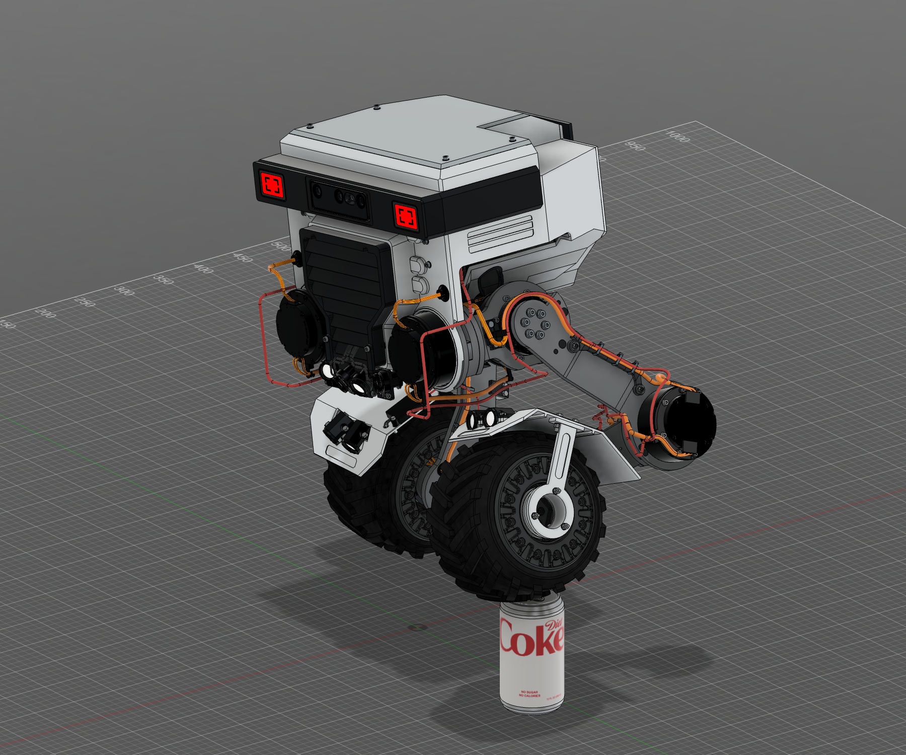
I also asked for the long added red lighting routes to go. They are removed from the legs and chassis, including hidden pose alternatives. Each fender now has a short local feed from its unused stationary wheel-actuator socket, carrying two power wires and two CAN wires, followed by local lamp leads. The original orange motor wiring stays intact.
Same R12 / completed cloud version 2
Native source and retained-state checks, five motion workflows, scoped articulation and full-angle wheel checks passed. The new local archive was reopened and exercised; one same-document cloud save completed as version 2. The original version-1 archive is preserved.
The hidden fender controller is still a 40 × 18 × 4.5 mm packaging allowance. Actual electronics, connector current and pinout, CAN configuration, printed fit/strength, and thermal/sealing behavior remain open. The updated mass model estimates 15.089 kg, with a 12.761–17.664 kg range; physical weighing, balance, and can strength are still to verify.
Build records: completed R12 sculpted-fender/local-lighting report and hash-bound evidence. This is CAD delivery for builder review; local archive reopening and cloud completion do not include an independent cloud download/reopen.
R12 · v1CAD complete
Fenders, eight lights, and a lower stance.
The overnight brief becomes a saved assembly: Sensor brackets eyes, matched finishes, fenders, lamps, cases, and wiring.+
Completed CAD handoffR12 · Complete overnight revisionFirst completed R12 version-1 assembly, before the sculpted-fender and local-feed update. Its original geometry and separate lighting routes are preserved here as build history.Native CAD / lamp envelopesR12 · All eight lamps, in contextNeutral front view shows four chin lamps and two per fender. The white lenses are a CAD material appearance; actual emitters, optics, current drivers, and heat paths remain unqualified.Verified CAD presentation poseR12 · Lower can-pose front viewThe saved connected pose uses 10° body bank and 13° outward raised-hip lean. Native contact and clearance checks support the CAD pose; can strength and powered balance still require physical evidence.Native CAD / conditional mass studyR12 · Stance and fenders from the sideFinal side view records the fender profile, can placement, and connected leg geometry. Estimated mass and support reactions guided the pose; measured mass and physical stability remain open.
Before heading to bed, I asked Codex to keep working on the same revision. The brief grew into compact faceted fenders, four lights below the grille, two in each fender, and a more believable can stance. The completed R12 brings those additions together in the native Fusion assembly.
The printed fenders have flat roofs, angled faces, and narrow outer supports around the inherited bearing envelopes. The original tire and wheel geometry stays intact. The chin lights follow the requested crossed layout: outer lamps aim inward and slightly down, while the inner pair aims down and outward. All eight lenses have a pure-white emissive CAD appearance.
The selected Sensor brackets eyes sit in a full charcoal brow and camera surround, matched to the grille. Twenty-two modeled aluminum parts have a matte-gray visual finish. The saved can pose uses a 10° body bank and 13° outward lean at the raised hip, applied through the connected assembly.
Three compact controller cases and dedicated lighting power/CAN routes are integrated, with localized lead passages in the removable intake pan. The electronics remain a design concept: actual LED and bearing parts, circuit design, fuse takeoff, connector ratings, and CAN interfaces still need qualification.
Completed CAD handoff / October 7
All added geometry and retained assembly parts were checked in native Fusion. Five motion workflows exercised the assembly, and the exact exported local archive was reopened and driven between neutral and the final can pose. One cloud save is complete as version 1. Offline checks cover 75 declared articulation samples and full-angle wheel envelopes within their stated scope.
A planning mass model estimates 14.78 kg, with a 12.61–17.33 kg range. It helped guide the stance; measured mass, physical balance, bearing loads, can strength, light output, and electrical behavior still need hardware validation.
After the first handoff / completed in version 2
After reviewing the fender concepts, I asked for a more sculpted shroud with vertical lamps, a straight leading edge with angled corners, and an inner mounting cover that hides the cable entry at the tibia.
I also asked Codex to remove the added red lighting harness along the legs and chassis, replacing it with a short local connection from each unused wheel-actuator socket to its fender controller: two power wires and two CAN wires. The original orange motor wiring stays. Electrical loading, protection, pinout, and the front-light input still need qualification. Those changes are documented in the version-2 entry above; this gallery records the completed R12 version-1 handoff.
Build records: completed R12 delivery report and machine-readable evidence; native receiving, archive, cloud, combined offline audit, and mass-study receipts. The local archive was reopened; independent cloud download/reopen is outside the reported scope.
R11CAD complete
Open guards. Red eyes. A familiar sense of scale.
The delivered cable-guard revision, posed on a 12-ounce can. Eye shapes and stance remain under review.+
Completed CAD handoffR11 · Delivered size-reference poseThe saved connected assembly with one tire on a 12-ounce Diet Coke can. This is CAD presentation evidence; a lower stance is now requested.Native CAD detailR11 · Open guards and compact knee protectionMatching open femur/tibia guards and local ties shown in the assembled leg context. Knee rails mount directly to actuator holes; physical fit and cable life remain unverified.Expression under further reviewR11 · Delivered red displaysThe delivered R11 red displays and segmented visors around the retained camera. Sensor brackets have since been selected for the next eye direction; native implementation is pending, and powered electronics remain ahead.CAD contact / visual referenceR11 · Tire-to-can referenceModeled rim, shoulder, tab, and Diet Coke artwork on the 66 mm × 122.22 mm prop. Native contact checks passed; can strength and robot balance require physical testing.
R11 turns my wiring feedback into matching open guards on the femur and tibia. Small local zip-tie slots let the cable lay into the guards, with no printed tube to thread it through. Compact knee rails bolt directly to the actuator holes, with close plug hoods replacing the projecting carriers and spacers.
Two recessed red displays flank the preserved camera. Their delivered static CAD appearance uses mirrored, segmented black visor graphics. A detailed 12-ounce Diet Coke can gives the assembly a familiar size reference: one tire meets the rim, while the other stays on the ground. The pose uses the connected joints.
Delivered and checked in CAD
Native geometry and ten joint workflows passed the build checks. The exact local Fusion archive was reopened and checked; one cloud save was reconciled as completed version 1. Scoped cable and service clearances were checked, including continuous wheel rotation at 17 declared joint positions. Physical fit, cable endurance, powered balance, and can load capacity still need measured validation.
The next direction: I chose the open, level “Sensor brackets” eye shapes and asked Codex to aim close to normal ride height in the can pose. The raised leg can lean outward a little if needed. That direction led into R12; the images here document the delivered R11 state.
Build records: R11 final delivery and verification report, completed October 6; subsequent builder feedback. The can is a CAD presentation prop. Pose-specific cable displays are static and do not deform automatically.
R10CAD complete
Cable carriers, bolted into the design.
Openable carriers and actual wheel-bore routing, with a camera/body preview for review.+
Completed carrier CADR10 · Complete carrier revisionBolted carriers and orange neutral wiring in the completed CAD assembly. Camera and body details remain visual previews.CAD detailR10 · Leg-carrier reviewFemur, knee, and tibia carriers shown with adjacent assemblies hidden. Use the exterior view for their surrounding installed context.Visual reviewR10 · Camera and brow previewCentered enclosed OAK-D Pro W with restrained body detailing. Attachment, heat transfer, and optical field of view await review.
After the R9 cleanup, I wanted the cable supports to have real attachments and removable covers. The femur and tibia now use bolted, openable carriers. Knee half covers protect the plugs on the stationary motor housing while leaving the moving cable spans free.
The wheel conductors follow the actual metal bore and intact bushing. The planned assembly order feeds the conductors through first, closes the channels, and then installs the terminated connector. Orange insulation makes the installed neutral cable routes easy to follow.
The centered enclosed OAK-D Pro W and restrained front/side details are included as visual previews. Camera attachment, heat transfer, and optical field of view still need review and qualification.
The completed CAD handoff
158 documented leg poses, continuous wheel rotation in the declared domains, 30 native motion workflows, and seven workflows after archive reopening. The editable archive was reopened and checked, Fusion cloud version 1 finished processing, and R9 stayed unchanged.
Physical material/process strength, fit, practical tooling, wire life, electrical integration, cooling, and commissioning remain open. The six flexible cable spans are pose-specific CAD displays.
Build records: R10 final delivery and verification report. Completed October 6, 5:46 pm Eastern.
R9CAD complete
Conceal the stops. Clean up the wiring.
A more compact mechanism, with the original joint datums preserved.+
Completed CAD revisionR9 · Complete assemblyConcealed stops, tighter cable routing, and downward louvers in the completed CAD revision.CAD detailR9 · Inside the jointsA cutaway shows how the stops and wiring sit close to the joint geometry.
My review was specific: bulky stop hardware and exposed wire loops distracted from the robot and made the design harder to build. R9 brings six stop assemblies into the joints and organizes routing at 14 connector positions. Downward louvers screen the fan while keeping open angled channels.
The handoff checked 30 native motion workflows, the installed geometry of 286 selected parts, and a reopened editable Fusion archive. Cloud saving finished separately. That gives us a durable CAD baseline to review and build from.
What this establishes
Checked CAD geometry, assembly ownership, motion cases, and saved files. Physical stop loads, cable life, airflow, fit, and commissioning still need measurements.
Build record: R9 completed CAD revision and verification. Completed late October 5, Eastern time.
R7–R8Integration
Review the battery, shell, and travel together.
A complete package exposes the details that still need another pass.+
Completed CAD revisionR7 · Before the compactness reviewVisible cable loops and prominent stop assemblies prompted the next iteration.CAD cutawayR7 · Battery packagingWrap hidden to review the holders, cells, nickel connections, and BMS placement.Intermediate design studyR8 · Smaller stops, same scaleThe R7/R8 geometry comparison explores lower receivers and a formed tongue. R8 remained an intermediate checkpoint.
R7 brings the battery holders, structural frame, shell, stops, and cable routes into one CAD review package. Battery service space and fit coupons are documented alongside the actual components. Joint travel gets explicit limits.
Wires have to survive articulation, so selected poses are checked with matching cable geometry. The CAD cable display is pose-specific; it does not automatically flex through every manual joint edit.
R8 is a saved intermediate checkpoint for smaller stops and improved routing. It retains unresolved connector fan-outs and pigtail approaches. Those open items lead into R9 rather than being called a finished release.
Save a useful assembly, then test the tools on real geometry.+
Saved CAD checkpointR6 · Face and wire exitsA wider integrated face intake and lower-profile cable attachment points.
R6 integrates the face and compact wire exits. A travel checkpoint records which changed-part checks finished, which cable sweeps are partial, and what has actually been saved. That makes the next session a continuation of the work.
A parallel SteveCAD experiment carries an R6 source representation into another workflow. Linked part builds and an actual grille edit-and-restore work, but full-assembly generation reaches the platform's 300-second budget. The project remains in Fusion while that limitation is documented.
Formed aluminum, stronger legs, and an intended path for the air.+
CAD revisionR5 · Cooling joins the designThe first cooling-intake integration accompanies further structural refinements.CAD cutawayR5 · Beneath the shellFormed brackets, electronics layout, and the intake assembly shown for review.
Bulky tie blocks give way to formed sheet parts. Leg plates become thicker and wider after load and deflection screening. Battery restraints, intake, fan transition, internal baffle, and rear exhaust become part of the same assembly.
Laser cutting, press-brake forming, machining, and engineering-filament printing shape the choices. The shop's tooling and bend information are inputs to the design, along with the robot's appearance.
Flat-pattern and print-review artifacts are prepared, while bend coupons, real airflow, temperatures, and assembled fit remain future checks.
Build records: R5 refinement handoff; load and thermal reviews.
R4Structure
Give the hip loads a shared backbone.
Continuous structure replaces separate supports—and adds a mass tradeoff.+
CAD cutawayR4 · A shared backboneA cutaway of the hip supports, plate, and assembly hardware behind the shell.
A continuous quarter-inch aluminum web, deeper cheeks, and ribbed connections tie the hip supports into a shared chassis. The change addresses the load path instead of only improving the exterior.
It also adds weight. Codex compares estimated mass, joint loading, and idealized stresses so the stronger-looking structure can be assessed against its cost to the rest of the robot. Physical strength qualification remains ahead.
Build records: R4 backbone handoff and engineering review.
R3Actuator baseline
Six 6248P legs. Two 4310P wheels.
The selected CAD configuration follows a comparison of torque, speed, and packaging.+
CAD revisionR3 · The new actuator baselineJ6248P leg actuators, formed legs, and an updated knee orientation.Kinematic CAD studyR3 · Exploring the crouchA pose from the native CAD motion study explores the mechanism’s folding geometry.
The leg baseline changes to six Damiao DM-J6248P-2EC actuators. Two 24 V DM-J4310P-2EC drives remain at the wheels. Knee outputs face inward so the upper and lower legs can pass during a deep crouch.
The selection follows research into holding duty, load-dependent speed, motor mass, interfaces, and available packaging. The earlier Unitree and larger Damiao combinations stay in the record as alternatives considered.
A local supported MuJoCo demonstration makes speed saturation visible at normal playback. A deliberately excessive wheel request reaches about 183 rpm; an excessive knee request reaches about 57 rpm under the model's declared limits. The yellow support guide constrains body roll and pitch, and self-collision is disabled for this isolated study.
These are simulation estimates for a supported speed demonstration. Autonomous balance, fresh policy training, and measured hardware performance are future work.
Build records: R3 overnight review; final actuator-speed readout.
MotionReview workflow
A mechanism you can actually watch.
Playback has to work before a motion study can be useful.+
An early custom Fusion playback controller crashes. The workflow moves to a native Motion Study authored through the application, then exercises play, pause, resume, restart, and orbit while playing.
The saved study and archive are reopened. The result becomes a short, silent X-ready edit that leads with motion and follows with a faster orbit. The clip shows kinematic CAD movement.
Build records: native playback repair result; September 29 edit and verification receipts.
R2Human review
Keep the character. Lose the bulky legs.
Slimmer formed plates, rearward hips, and a lower driving stance.+
CAD revisionR2 · Slimmer legsFormed-aluminum legs and a more crouched driving stance, shaped through my review.
I asked for slimmer legs and a compact form closer to the original Rolie. Codex revised the geometry toward formed 5052-H32 aluminum plates, shifted the hips rearward, and lowered the neutral hip height to 320 mm.
Appearance feedback becomes mechanical direction. The revised layout is checked with actual joint ownership and selected clearance poses, keeping the original source intact.
Build record: R2 final CAD verification.
R1The starting point
An existing idea becomes an editable robot.
Recover the concept, define the behaviors, and build a real assembly.+
Original conceptThe original conceptThe preserved SolidWorks concept that set the character and visual starting point.CAD revisionR1 · First Fusion assemblyActuator layout, articulated legs, reused rover wheels, and an early chassis.
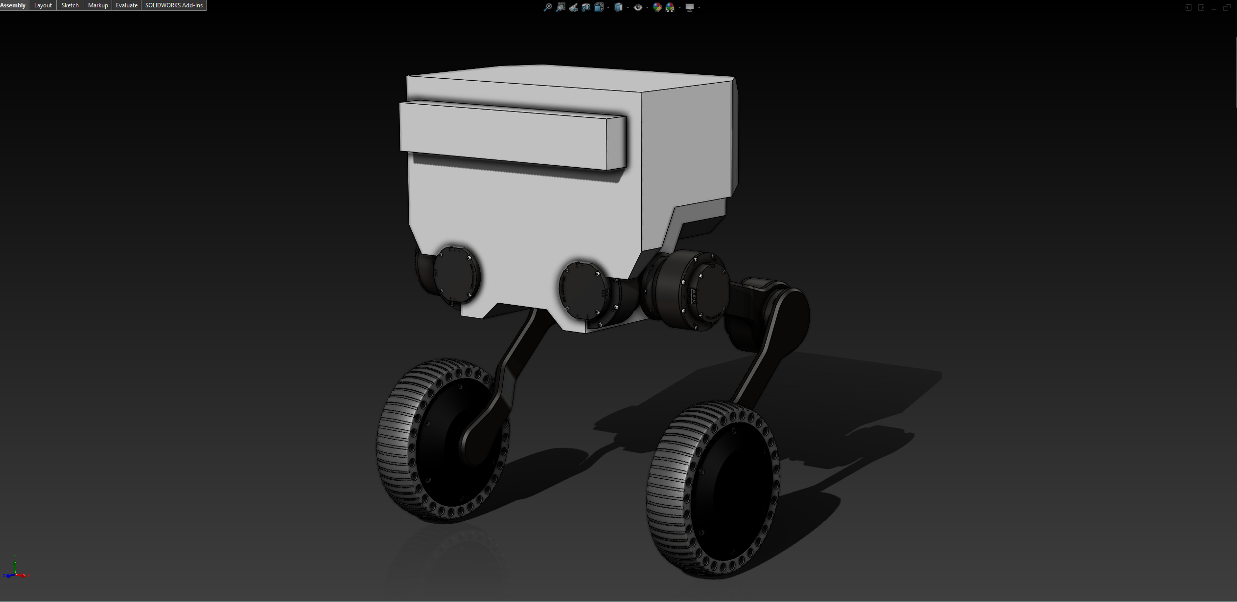
The starting point is an unfinished SolidWorks wheeled-biped concept. Its familiar body and the builder's rover wheels guide the new assembly. The intended behaviors include smooth crouched driving, wheel-held stepping, and eventually curbs and small stairs.
R1 uses six Unitree GO-M8010-6 leg motors and two Damiao wheel drives. Eight native revolute joints make the mechanism inspectable. Static wheel raises and sampled poses check the layout; later actuator research changes the leg baseline.
Build records: mini-TRON1 development plan; September 27 overnight CAD handoff.
02 / In motion
Show the work.
The latest R12 v5 three-view edit, earlier X-ready clips, and the supported actuator-speed study. Each clip identifies the design or simulation work it shows.
R12 v5 CAD / 16.4 sec
09 October 2026 · 1× playback · silent
The finished CAD, from three angles.
Exterior, exposed internals, then a close look at the fender and controller packaging. Three owner recordings are joined with idle sections removed, at their original speed.
Fusion camera movement around the current CAD model. Hidden covers reveal installed design geometry; this does not demonstrate a physical teardown or powered robot.
Two Fusion recordings from the completed compact-fender update: tire on the Diet Coke reference can, then normal standing. Dead time at both ends is removed, with the moving camera orbits joined at their original speed.
Version 3 can presentation and version 4 standing pose. The camera moves around static CAD poses; physical assembly and powered balance are still ahead.
A Fusion orbit I recorded around the delivered R11 can pose. Idle sections at the beginning, middle, and end are trimmed; the moving portions play at normal speed.
The camera moves around a static CAD presentation pose. The can is a size reference; powered balance and load capacity still need physical testing. Eye shapes, finish, and stance evolved in R12 after this recording.
R10 CAD / 16.3 sec
06 October 2026 · 1× playback
An orbit of R10.
An orbit I recorded in Fusion, showing the bolted carriers, orange wiring, and camera/body preview. The idle lead-in and ending are trimmed; playback stays at normal speed.
A CAD viewport recording of the completed carrier revision. Camera and body detailing remain visual previews.
CAD / 18.5 sec
06 October 2026
Outside, then inside.
An exterior orbit followed by the aluminum backbone and battery. Silent X-ready edit; the orbit is accelerated.
CAD / 12.1 sec
29 September 2026
Crouch. Extend. Roll.
The mechanism in a Fusion motion study. Silent X-ready edit with an accelerated orbit.
Supported simulation / 53.8 sec
29 September 2026 · 1× playback
Where the speed runs out.
A MuJoCo study of wheel and joint limits. The visible guide constrains torso roll/pitch; self-collision is disabled. Read the on-screen request and measured speed together.
A supported actuator study; physical measurements and learned locomotion are still ahead.
03 / The robot
What we're building around.
The current CAD baseline and the next onboard-compute step. Selected components still need bench and assembly checks.
Frame and battery reference · R9 CAD view
01 Leg joints
6 × Damiao DM-J6248P-2EC
Hip roll, hip pitch, and backward-folding knee on each side. Selected CAD baseline since R3.
02 Wheel drives
2 × Damiao DM-J4310P-2EC · 24 V
Rover-derived wheels and tires inform the packaging, load path, and motor interface.
03 Structure + power
Aluminum backbone · custom 21700 pack
Formed and machined parts under a printed shell. Battery holders, service space, and fit coupons are modeled.
04 Incoming compute
Codex-branded Raspberry Pi 5
The OpenAI developers team's special board is planned for low-level robot compute. Arrival and robot integration are still ahead.
Why did the actuator choice change?+
The first assembly used Unitree GO motors, informed by the builder's experience with a Go2. An aggressive knee-load screen and uncertain continuous holding duty prompted a wider comparison.
Codex explored reduction, battery mass, and several Damiao families. Larger 8009P/8006 combinations were a research shortlist; the 6248P became the selected leg candidate after weighing torque, speed, mass, control interfaces, and packaging together. The 4310P wheel candidate remained.
Published peak torque was one input. Sustained duty, exact driver revision, bearing loads, and temperature under the mounted workload still have to be checked. The design record establishes a CAD/simulation selection.
04 / Bill of materials
Keep the parts with the decisions.
A working BOM that grows with the build. Quantities below describe the design candidate; purchase and physical acceptance are tracked separately.
Whole-robot fasteners, harness lengths, and final fabrication parts are being reconciled.
Maintained from build records + builder updates · Reviewed
05 / Work list
The work list.
A provisional work list from the build records. We’ll refine the fuller backlog together as the build progresses.
Loading work list…
Maintained by Codex as the build progresses · Reviewed
06 / Me + Codex
The conversation is part of the design.
I set the intent and challenge assumptions. Codex researches, models, checks, and brings back the next thing for me to inspect.
01
Set the real constraints.
Start with the original concept, wanted behaviors, available wheels, battery cells, and shop capabilities. Keep open decisions visible.
Me: priorities and context Codex: options and engineering questions
02
Review something concrete.
Look at the actual assembly. Slimmer legs, rearward hips, hidden stops, and a face that screens the fan came from specific human feedback.
Me: visual and mechanical direction Codex: revised native CAD
03
Use a narrow experiment.
When stepping attempts did not demonstrate the goal, the next question became actuator speed. A supported study isolated that question and showed saturation.
Me: choose the question Codex: expose the result and its limits
04
Make the next review durable.
Check real joints and the review controls. Reopen the editable archive. Reconcile cloud saving. Record partial work so the next session can pick it up.
Me: inspect and steer Codex: verify and preserve evidence
A recurring lesson
“Looks right” starts a review. “Works in the assembly” needs evidence.
07 / Ahead of us
From CAD to a working robot.
The work shown here is design and simulation. The physical build and training will add their own results to this journal.
Next design review
Develop the compute and perception revision.
R12 v5 remains delivered. The new cycle integrates AGX, AIRY, chin depth sensing and successor body electronics. Complete accepted CAD and routed-board handoffs, then qualify fabrication, harnesses, service and power before hardware bring-up.
Physical build
Make parts. Check fit. Bench the hardware.
Manufacture the structure, qualify prints and battery assembly, measure actuators, and verify interfaces.
Robot bring-up
Install the Pi. Establish calibration and control.
Bring up compute, motor communication, sensing, and measured joint references before operating trials.
Learning + demonstrations
Train, evaluate, and record what works.
Start with a reproducible learning baseline, then work toward smooth driving, crouch, stepping, and defined curb cases.
08 / Open design
Built to be shared.
We plan to open-source the finished design and provide CAD files so others can inspect the mechanism, adapt it, and build on the work.
Planned release
Editable CAD + build documentation
The release will bring mechanical CAD, KiCad projects, schematics and build documentation together with the BOM and revision notes. Component pages keep each file family with its design revision.
CAD download
Available when the finished design is released
Source repository
Link to be added at release
License
To be selected before release
Behind the build
Join the conversation.
I share design clips and build notes on X. Follow along, ask questions, and let me know what you think as Alpha Rolie takes shape.
This journal was assembled on October 6, 2026 from the project's dated plans, CAD handoffs, verification records, and original media receipts. New milestone times use Central time; earlier explicitly labeled Eastern times remain historical. Date ranges cover work spanning more than one day.
R12 version 5 is the latest completed CAD delivery, integrating the 6S6P battery, rebuilt chassis and lighting. Versions 1–4 and the travel/progress checkpoints remain history. Native source comparisons, motion and actual local archive reopening passed; cloud completion is recorded separately from cloud download/reopen. The R3 fender board is a checked engineering candidate, while the body board has seven remaining connections. Conditional board service, failed tested motor-plug/cover paths, factory processes and physical qualification remain explicit. The clips are edits of owner recordings, not physical robot demonstrations.
Selection for the OpenAI program and the incoming branded Pi are information supplied by the builder. “Codex Physical Build Challenge” is the working program name to confirm before a public release.
Journal entries are summaries of the build records. The recurring lesson in the process section is editorial copy, rather than a verbatim quotation from a build conversation.